Throughout all these years of experience working with pump systems of various types, the engineers at Protech Continental have observed that helical screw pumps tend to lose pumping capacity progressively and significantly with continued use. In addition, corrective maintenance, which was usually a direct responsibility of the customer, entailed high operating costs during the years following the acquisition.
For this reason, we aim to offer our customers a more efficient and cost-effective alternative that allows them to reduce these maintenance costs to the maximum without sacrificing performance.
With the aim of offering maintenance without sacrificing performance, at Protech Continental we analyse in depth the various types of faults and recurrent failures in progressive cavity pumps (helical pumps). Our experience has shown that most problems occur in pumps subjected to high rotational speeds, with monobloc designs, simple sealing systems and mechanically fragile joints.
This type of mechanical configuration is, in many cases, the main cause of the most common failures in this type of pump.
In our technical study, we identified the following common problems with helical pumps:
- Leaks in pump shaft sealing systems.
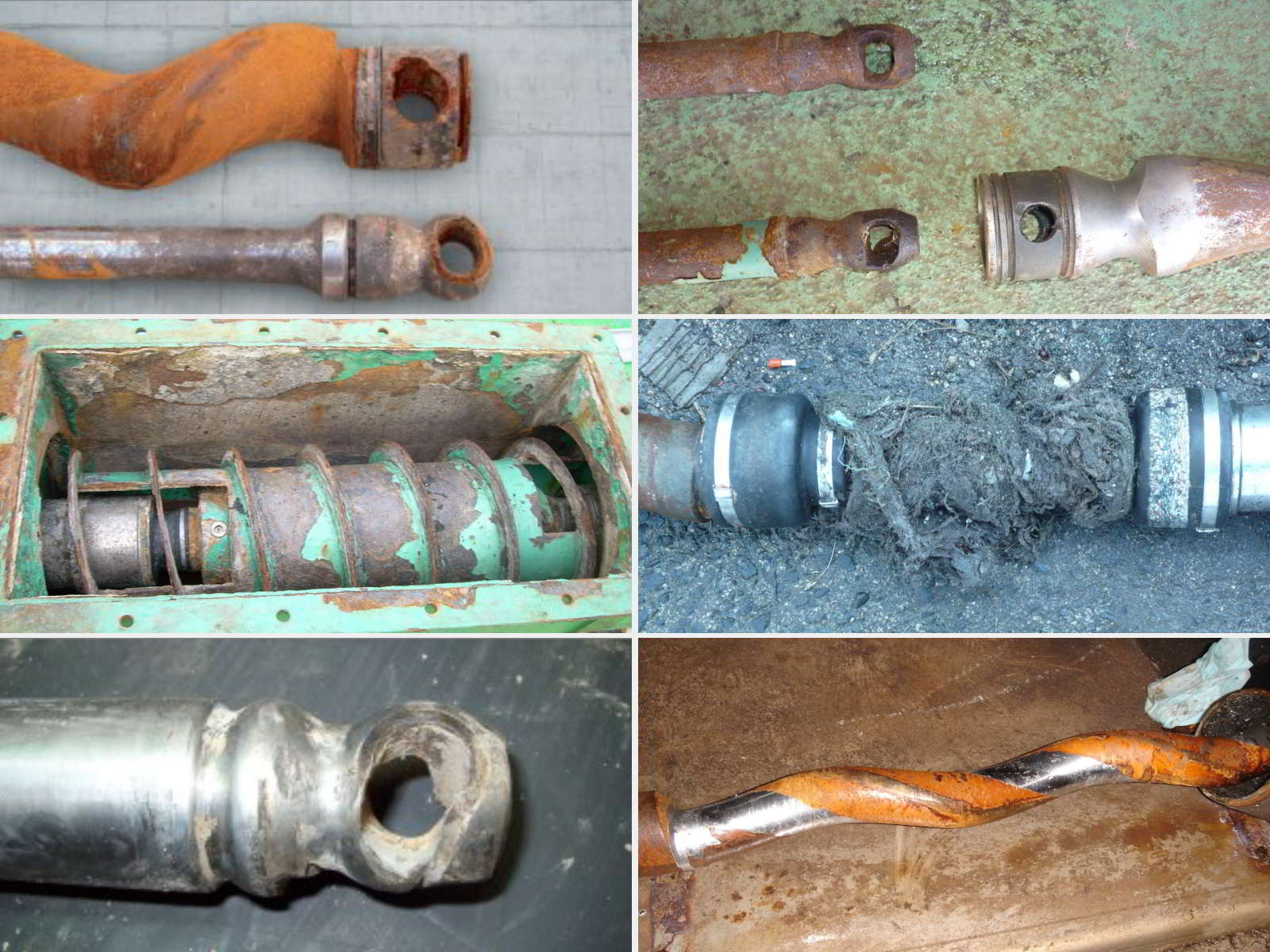
- Winding of hairs and fibers in cranks and mechanical seals.
- Premature wear of rotors and stators.
- Broken cranks and joints.
- Wear on drive shafts.
- Failure of reducers.
- Formation of vaults during pumping of dehydrated sludge.
- Rapid loss of flow.
- Complex and costly component replacement.
- Low level of automation and minimal technical assistance.
Faced with this scenario, at Protech Continental we set out not only to catalogue and analyse each of these problems, but also to design a real and effective solution. Thus, the first screw pump on the market capable of maintaining a constant flow rate and ensuring virtually maintenance-free operation was born.
Below, we explain in detail the design solutions that Protech Continental has validated through the design and construction of our «PREMIUM Series» helical pumps.
Mechanical design solutions in helical pumps
Problem: Monobloc designs.
Solution: Integration of a bearing support.
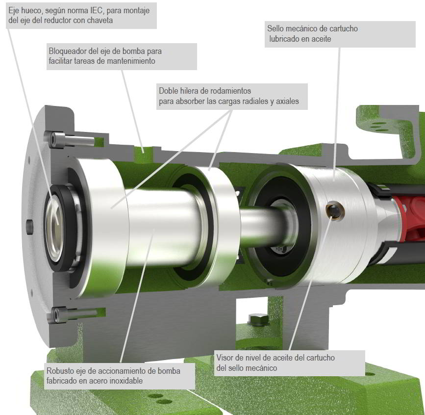
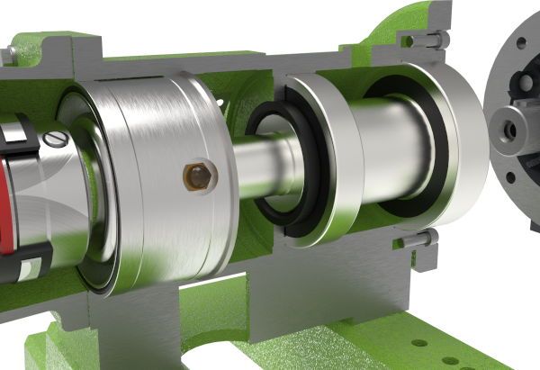
Unlike the pumps in monobloc execution, mounting a ball bearing support, type 2RS double row, we can absorb all radial and axial loads generated by the rotor of the pump when rotating. These loads will be higher the higher the speed of rotation and the pressure in operation.
In the usual monobloc designs, the loads are absorbed in the bearings of the reducer and not of the pump, by not incorporating this component “damper”. Therefore, it is common for gearboxes to suffer fatigue and breakage over the years.
The assembly from the bearing holder to the reducer has to be carried out by means of a completely standardized connection. The reducer shaft enters the hollow shaft of the pump, producing drag through a keyway.
By means of an axle blocker, located at the top of the support, we can block against rotation the equipment while we carry out the tasks of disassembly of the stator.
Problem: Fragile transmissions
Solution: Dual-link transmission
One of the least known mechanical aspects of a screw pump is its transmission. Currently, most of this type of pumps on the market incorporate a closed rod and bolt transmission system.
This type of bolt, housed inside the eccentric cap, is responsible for generating the movement required by the pump during its rotation and pumping.
Because of this, after only months of operation, with millions of turns made, there is continuous wear and deterioration, also increased by the operating pressure in the installation. We will avoid this wear of the pump by mounting a double transmission of type cardan with bearings of needles lubricated in grease.
With the solution of a maintenance-free transmission, during the service life of the equipment, we should only pay attention to the state of the protective rubber shaft, provided with a textile reinforcement, which will integrally protect both cardanes. In addition, its condition can be checked quickly and easily by means of side inspection and recording covers.
For the disassembly of the rotor, or on its other side of the drive shaft, it will not be necessary to disassemble the protective sleeve, which will greatly streamline maintenance tasks.

Problem: Rotor and stator geometries “L”, “LT”, “P” and “D”
Solution: “S” geometry
Various rotor and stator geometries are available on the market among different screw pump manufacturers.
One of the geometries most introduced in the market is the so-called “L” (Long pitch).
It is characterized by having a high pumping capacity per rotation and is designed for low abrasive fluids or for operation with low pressure. These are rotors with very smooth thrust angles and circular cross-section.
From this, over time, new tri-lobular geometries were developed, much more hydraulically efficient than the “L” ones, providing even greater flow rate by rotation. In this case, the rotor section is oval. They are hydraulics called geometry “LT”, “P” and “D”. In these geometries, the cavities are traversed twice with each rotor revolution, which in combination with a larger cavity volume, compared to “S” geometries, results in up to 300% higher flow rates.
In other words, these three types of geometry can be mounted on the same screw pump while maintaining a common mechanism for all three hydraulic assemblies.
Examples:
Pump size A + hydraulic “S” = 10 m3/h
Pump size A + hydraulic “L” = 20 m3/h
Pump size A + hydraulic “LT-P” = 30 m3/h
Bomba tamaño A + hidráulica “S” = 10 m3/hBomba tamaño A + hidráulica “L” = 20 m3/hBomba tamaño A + hidráulica “LT-P” = 30 m3/h
At Protech Continental, we are committed to a single type of geometry: the “S” geometry.
It is undoubtedly the most resistant to abrasion and stable against pressure. These are not geometries designed to obtain a competitive product economically for tenders in new works, but to achieve the minimum possible maintenance and a long service life of all its components.
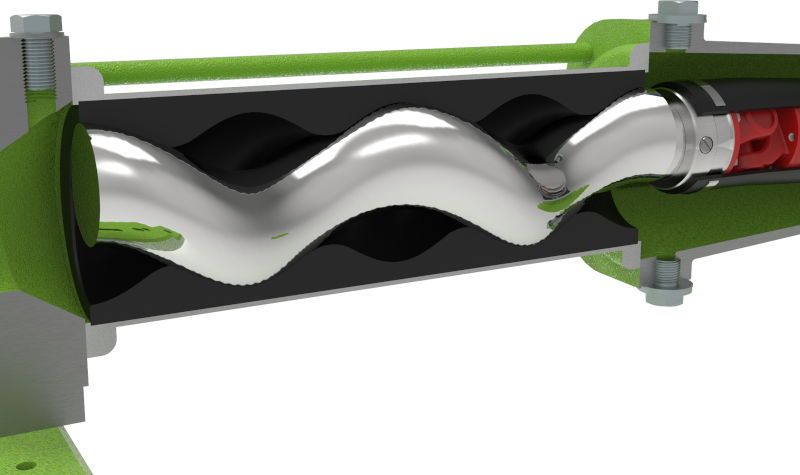
In addition, the “S” geometry has a large spherical solids pitch, making it ideal for pumping highly viscous fluids and sludges. It is therefore a design designed for the end user, associated with low maintenance costs by minimising corrective unplanned shutdowns.
Problem: Simple mechanical seals or gaskets.
Solution: Oil-lubricated cartridge mechanical seal.
In the event of leaks in the pump shaft seal, we believe that fitting a cartridge mechanical seal lubricated with mineral oil is the best option.
We bet on the use of seal faces manufactured in silicon carbide and bathed by a lubricating fluid, unlike the traditional simple seals, which do it by the fluid itself to pump, usually with the presence of suspended solids. With this solution, the external springs or springs in contact with the fluid disappear, which are points susceptible to curling of hairs and fibers, causing leaks and breakages.
With a cartridge housed inside the bearing holder, replacing it will be extremely easy and fast.
With this system, the surface of the pump drive shaft will never be damaged or scratched, a common problem in pumps with forced feed for dehydrated sludge, which usually incorporate a sealing system by means of packing.
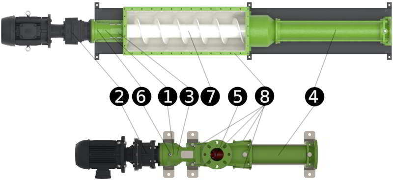
8 Technical characteristics of a screw pump with premium mechanics
- Robust construction with bearing support.
The speed of rotation of the pump together with the eccentric movement of the rotor, generate radial and axial loads that are transmitted to the bearings of the gearbox, causing their fatigue and causing failures in the wheels and sprockets. These forces can be avoided by mounting a sturdy double-row bearing support to absorb the forces generated, thus protecting the reducer from overload failures.
- Standard drive.
The coupling system between pump and reducer must be made by means of a keyway and an IEC standard shaft, in order to facilitate and save maintenance work. - Oil-lubricated cartridge mechanical seal.
The sealing system shall be based on an oil-lubricated cartridge mechanical seal. The faces of the seal must be bathed by a clean and lubricating fluid unlike traditional seals that are lubricated by the fluid to be pumped.
- Highly wear-resistant rotor and stator geometry.
The choice of geometry with passage of solids and rubber quality, depending on the fluid to be pumped, together with a low rotation speed, will contribute to a much higher service life of the hydraulic assembly. - Transmission cardan with needle bearings.
As a force transmission system, it is more optimal to mount a cardan system with grease-lubricated needle bearings. It is a simple, highly robust and maintenance-free system. The cardan is not part of the regular maintenance of progressive cavity pumps, because it has a long maintenance-free life. Both cardanic transmissions are protected by a protective rubber sleeve with textile reinforcement.
- Axle Blocker.
By incorporating a lock of the pump shaft, which prevents the rotation of this, we are able to facilitate the tasks of replacing the stator. - Optimized feed screw design.
With a robust design of the feed screw with a large diameter, a generous pitch and by a blade of great thickness and height, we can guarantee the push of the product to be pumped towards the stator and rotor cone. - Large inspection and registration caps.
Including large covers for transmission inspection and cleaning the inside of the pump, maintenance is greatly facilitated by not having to disassemble the equipment.